Table of Content
As per the datasheet of ULN2003 pin 9 is VCC and PIN 8 is GND but in the circuit there is no VCC given to ULN2003 then how the circuit will work. 12 we r going to use 0.5 or0.75 Sq.mm 3 core cable max 80mtrs length from motor to over head tank. Now, this latching can be broken simply by applying a 0V to the base of the BC547. I really need for this thing to cycle between FULL and REFILL sensors and not cycle on and off when just the top sensor is wet or not.
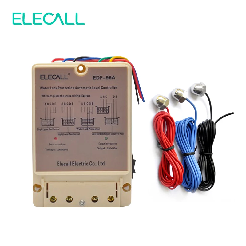
Simply use 2mm 316 stainless welding rod forced through a 1.5mm drilled hole in a good quality plastic fitting. It never rusts and is small enough not to be affected by too much water motion. In addition, your circuit can be driven by 3 or 4 volts, so , I used second hand 5 volt cell phone chargers to power them. These give plenty power to drive 6 volt relays and of course they have been designed almost bullet proof and are compact.
How To Make a Simple Water Level Indicator
This control has a small 12V coil relay whose contacts are rated at 10A 120V. You can select any relay to suit your water pump's power source. The above circuit has been presented on request from one of my followers, Prateek.
Through a process of elimination it turned out that removing the capacitor on pin 14 solved the problem. During the on period this output and the BC557 Collector voltages are at 12 Volts. This switches ON the LED marked LOW and switches OFF the LED marked OK.
Step 3 - Studying the Circuit Diagram.
If possible can you help me for supporting them please. Circuit is working nicely sir with a slight change, thanks for your support so kind of you. Sanjay, the shown circuit should fulfill your requirement as desired. When water is drained out, pin1 will be removed from water contact, removing zero from pin16, but still the relay will be off because pin10 is still zero. You can try implementing the circuit in the video and check whether it fulfills the first two objectives or not, then afterwards we can go for the 3rd objective. Thank you Pralhad, I think the first two objectives can be solved using the circuit which is shown in the video.

Yes they can be used but for society application I will recommend using float switch sensors. In all three ICs would be required constituting 16 gates, only 13 will be used and 3 will remain unused, the above precaution must be followed with these unused gates. The transistor relay switches OFF and hence horn#1. Or add two led for indication On AC and On battery.
Using BC337 and BC327 transistors and three relays
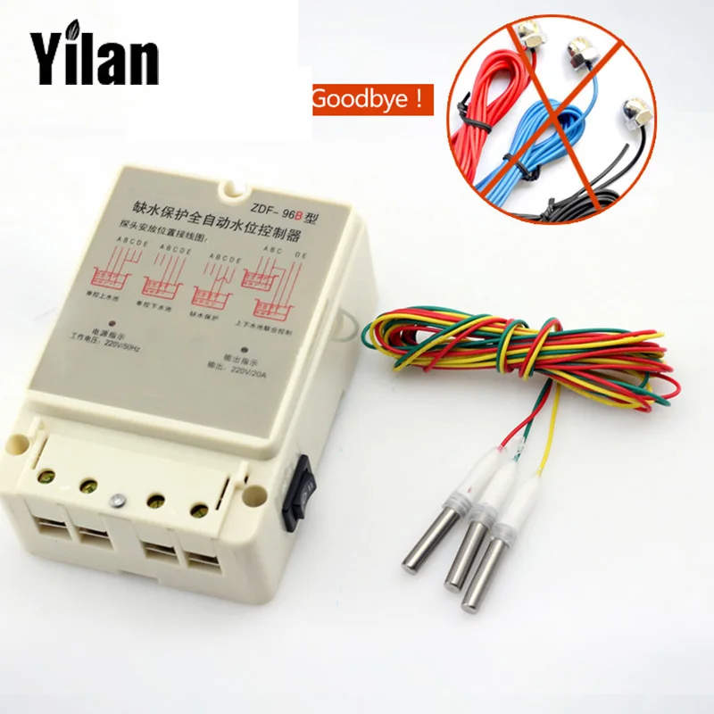
I have used GI Iron Rod as probe it has electrolyzed after some time and i need to change it every time so could you give me the right things which can be better for probe. You can put two 1N4007 diodes in series with the relay coil for cutting down 1.2 volts, this will keep the relay from getting unnecessarily warm. Check the circuit again by replacing the motor with a 100 watt bulb, if it works normally then the problem could be in the relay, or due to instability. Design and Implement a circuit that could give the status of 4 filling tanks when any two of the tanks need filling. The indication shall be implemented using a LED.
The circuit will need to be powered from a 12V adapter. It is really good to get all these information. I have same requirement of water indicator which I am going to make now.
Step 2: Set-up
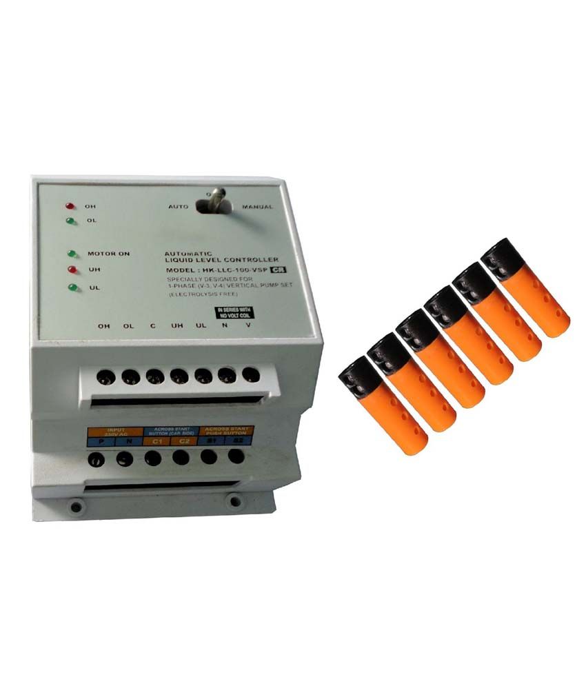
Identify Phase & Neutral wire in the Starter with “LINE TESTER” after switching ON the power supply. Identify two terminals of starter “OFF Button” usually a Red Push switches mounted on the door of the starter . Both relay gets on at this Stage which as a result breaks the connection between "NC" and "Common" of both relay. This is the reason which breaks the (+) voltage supply to the relay "C" and Main relay and both relay gets off which stops the motor.
I guess you can replace the relay with the SSR you mentioned. The 12V version draws like 20mA, well within the capacity of the transistor. I am just wondering if I can substitute a 100K resistor instead of getting one I don’t have in stock. If this voltage test proves successful, proceed to next step. I intended to build a kit for Club Jameco out of how I remembered this control worked and this is what this instructable is all about. Fill the jug a few inches from the top with water, insert the tube in the hole until it is not quite touching the bottom of the jug.
To simulating water consumption as water level goes down, remove the "High level" wire from the water container and nothing should happen. Then, remove the "low level" wire from the water container and the green LED should turn on and the relay should energize the water pump and the cycle will repeat. When the water level falls slightly below the higher level of tank. Higher relay gets off and the "NC" of the relay is now connected to "Common" pin. Now, In the Circuit the "NC" of the relay is connected to "NO" pin of main relay and the main relay is off because it is not getting any (+) voltage supply from medium level relay.
Here we will tell you How to Make Wireless water level indicators at home. We will build a wireless water level indicator using Arduino and an ultrasonic module in this project. The ultrasonic sensor is used to detect the range of the object from it. The ultrasonic sensor detects the presence of an object based on its distance from the module, which we can configure through various properties of the sensor.
Now short the two delay wires and insert it inside the sleeve firmly. This will introduce a 15 second delay for all ON operation. Repeat the steps from STEP 2 to STEP 5 for four to five times to ensure the correct operations.


No comments:
Post a Comment